

Overview
In this tutorial, we will design a circuit using a TRIAC and an optocoupler to create an IoT AC Light Dimmer or AC Fan Speed Controller using an ESP32 WebServer.
AC power runs most of our home appliances like lights and fans. Sometimes, we want to control these devices—for example, dimming a lamp or adjusting a fan’s speed. To control 110/220V AC power effectively, we use a TRIAC for phase control, which means turning it on only during a specific part of the AC wave.

Controlling AC loads is more complicated than DC because AC power changes direction at a frequency of 50/60Hz. To build an AC dimmer, we need to detect the zero-crossing points where the wave switches direction. We use a zero-crossing detector for this and adjust the phase and cycle of the wave to control the power delivered.
Most electronic components can’t handle direct contact with high-voltage AC power. So, we isolate the control circuit from the high-voltage side using optocouplers. These devices let us control the power safely without exposing sensitive parts to dangerous voltages.
In this project, we incorporate an ESP32 microcontroller to add IoT capabilities to our AC dimmer. By hosting a web server on the ESP32, we can control the dimming of the AC load remotely through a web interface. This allows for convenient and flexible control of appliances over a network, paving the way for smart home applications.
WARNING: This circuit is connected directly to the mains AC voltage. You must care about all safety precautions before using the device. If you are a beginner and without having the idea of using electronics appliances. Please avoid!
Bill of Materials
For this project, we will need the following components. The component list, footprint, and quantity are given below.
| ID | Name | Designator | Footprint | Quantity | Manufacturer Part |
|---|---|---|---|---|---|
| 1 | Capacitor 1uF | C1 | C0805 | 1 | |
| 2 | Capacitor 0.1u | C2,C4 | C0805 | 2 | |
| 3 | Capacitor 10uf | C3, C6, C7 | C0805 | 3 | |
| 4 | Capacitor 1uf | C5 | C0805 | 1 | |
| 5 | Rectifier DB107 | D1 | DIO-BG-TH_DB107 | 1 | DB107 |
| 6 | FTDI Connector | PROG | HDR-F-2.54_1X6 | 1 | |
| 7 | Transistor BC847 | Q1,Q3 | SOT-23-3 | 2 | 2n3904S-RTK/PS |
| 8 | TRIAC BTA16 | Q2 | TO-220-3 | 1 | BTA16-800CW |
| 9 | Resistor 330R | R1,R4 | R0805 | 2 | |
| 10 | Resistor 47K | R2,R3 | R0805 | 2 | |
| 11 | DNP (10K Resistor) | R5 | R0805 | 1 | |
| 12 | Resistor 10K | R6,R7,R8 | R0805 | 3 | |
| 13 | Optocoupler PC817C | U1 | DIP-4 | 1 | PC817C |
| 14 | MOC3052SR2M | U2 | SMT-6_6.3MM | 1 | MOC3052SR2M |
| 15 | HLK-10M05 | U3 | PWRM-TH_HLK-10M05 | 1 | HLK-10M05 |
| 16 | ESP32-WROOM | U4 | WIFIM-SMD_39P | 1 | ESP32-WROOM-32-N8 |
| 17 | HT7333-7 | U5 | SOT-89-3 | 1 | HT7333-7 |
| 18 | Terminal Block 2 Pin | U6,U7 | CONN-TH_2P-P5.00 | 2 | TY500-5.0-02P-14-00AH |
ESP32 AC Dimmer Circuit Diagram & Hardware Design
The circuit for the “IoT AC Dimmer using TRIAC & ESP32” consists of three main sections: the power supply, control circuit, and AC load control.
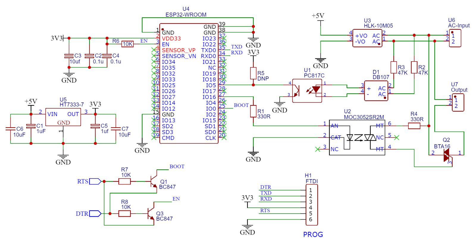
The power supply section uses an HLK-10M05 module to step down the AC mains to a 5V DC supplY, further regulated to 3.3V using an HT7333-7 regulator to power the ESP32 module. Capacitors are used for filtering to ensure a stable DC output.
The ESP32 is the brain of the circuit, hosting a web server to control the dimming function. The zero-crossing detection is achieved using an optocoupler (PC817C) connected to the AC mains. The zero-crossing signal helps the ESP32 to synchronize with the AC wave and control the TRIAC’s firing angle via a MOC3052 opto-isolated TRIAC driver. The ESP32 triggers the MOC3052 through a GPIO pin, which then controls the main TRIAC (BTA16). This TRIAC regulates the power supplied to the load, allowing precise control of brightness or speed.

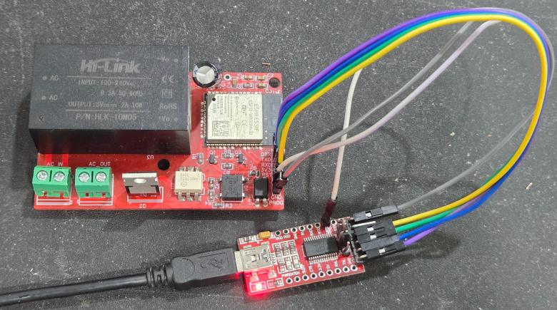
To program the ESP32 raw chip, the FTDI pin is provided. We can connect an FTDI Module (USB-to-TTL Converter) to program the ESP32 Chip directly.
Project PCB Gerber File & PCB Ordering Online
We have designed the PCB using the EasyEDA Software. It took quite a lot of time fixing all the issues in the PCB but still we managed to design a complete working custom PCB.
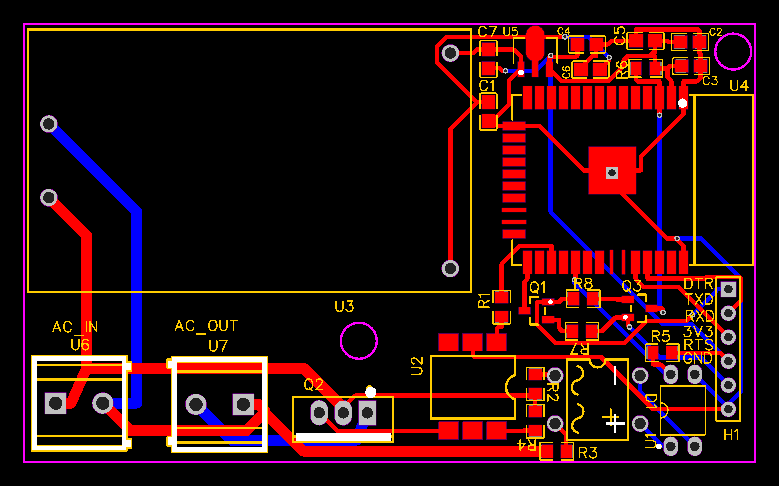
The top part of the PCB design looks like this.
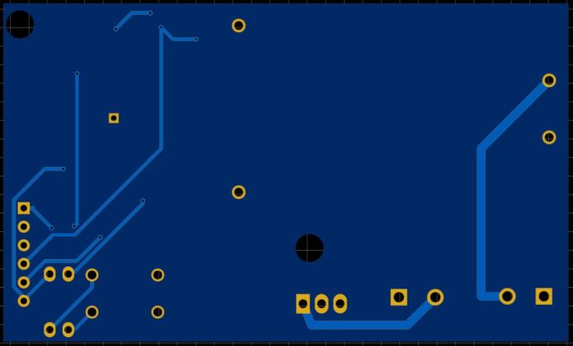
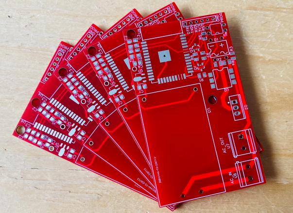
The bottom part of the PCB board looks like this.
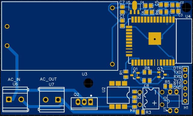
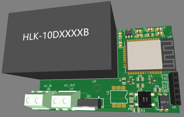
Here is the 3D View of the PCB from the front side.
The Gerber File for the PCB is given below. You can simply download the Gerber File and order the PCB from ALLPCB at 1$ only.
You can use this Gerber file to order high-quality PCB for this project. To do that visit the ALLPCB official website by clicking here: https://www.allpcb.com/.

You can now upload the Gerber File by choosing the Quote Now option. From these options, you can choose the Material Type, Dimensions, Quantity, Thickness, Solder Mask Color and other required parameters.
After filling all details, select your country and shipping method. Finally you can place the order.
PCB & Hardware Assembly
After ordering the PCB, it took almost 5 days and I got my PCB.

The PCB quality from ALLPCB is superb with very premium quality. That is why most people trust ALLPCB for PCB/PCBA Services.
First solder all the SMD components like resistors, capacitors, transistors, voltage regulators & diodes.
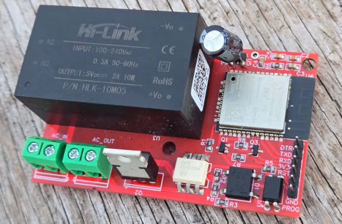
After soldering all these, you can solder the ESP32 raw chip. The final stage would be soldering all the through-hole components like Optocoupler IC, terminal block, male-female headers, and AC-to-DC Converter Module.
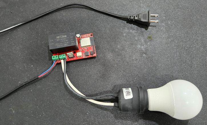
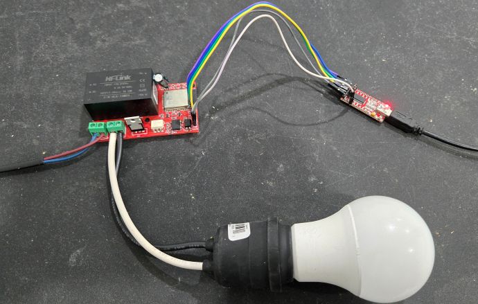
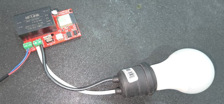
Connect the AC input Cable at the input terminal of AC IN. Also connect any load like Filament Bulb or AC Fan at the output terminal of AC OUT.
After soldering all the components, the ESP32 IoT AC Dimmer Board is ready for the test. You can upload a blink sketch by connecting a USB-to-TTL Converter Module.
Now we can move to the main part of the project and write a C/C++ & WebServer Code for ESP32 IoT AC Dimmer project.
Source Code/Program
This code implements an IoT-based AC dimmer using an ESP32, allowing users to control the brightness of an AC load (like a lamp or fan) through a web interface. The ESP32 connects to a WiFi network and hosts a web server that provides a user-friendly control page. On the web page, users can adjust a slider to set the dimming level (0 to 100%), which is sent to the ESP32 via HTTP GET requests.
The circuit detects the AC mains’ zero-crossing points through an interrupt, ensuring synchronized control of the TRIAC. Based on the dimming level received from the web interface, the set_power function calculates the TRIAC’s firing angle, and the zero_cross_int function controls the TRIAC to adjust the power delivered to the load. This allows for smooth dimming of the connected AC device.
From the following lines in the below code, change the WiFi SSID and Password and replace it with yours.
|
1 2 |
const char* WIFI_SSID = "**************"; const char* WIFI_PASS = "**************"; |
Here is the final code that you can copy, modify and upload to the ESP32 Chip.
|
1 2 3 4 5 6 7 8 9 10 11 12 13 14 15 16 17 18 19 20 21 22 23 24 25 26 27 28 29 30 31 32 33 34 35 36 37 38 39 40 41 42 43 44 45 46 47 48 49 50 51 52 53 54 55 56 57 58 59 60 61 62 63 64 65 66 67 68 69 70 71 72 73 74 75 76 77 78 79 80 81 82 83 84 85 86 87 88 89 90 91 92 93 94 95 96 97 98 99 100 101 102 103 104 105 106 107 108 109 110 111 112 113 114 115 116 117 118 119 120 121 122 123 124 125 126 127 128 129 130 131 132 133 134 135 136 137 138 139 140 141 142 143 144 145 146 147 148 149 150 151 152 153 154 155 156 157 158 159 160 161 162 163 164 165 166 167 168 169 170 171 172 173 174 175 176 177 178 179 180 181 182 183 184 185 186 187 188 189 190 191 192 193 194 195 196 197 198 199 200 201 202 203 204 205 206 207 208 209 210 211 212 213 214 215 216 217 218 219 220 221 222 223 224 225 226 227 228 229 230 231 232 233 |
#include <arduino.h> #include <WiFi.h> #include <WiFiClient.h> // ESP32 #define SCR_Pin 16 #define ZCD_PIN 5 #define AC_CTRL_OFF digitalWrite(SCR_Pin, LOW) #define AC_CTRL_ON digitalWrite(SCR_Pin, HIGH) unsigned char dim = 0; const char* WIFI_SSID = "**************"; const char* WIFI_PASS = "**************"; WiFiServer server(80); const char mainPage[] PROGMEM = R"rawliteral( <!DOCTYPE HTML><html> <head> <meta name="viewport" content="width=device-width, initial-scale=1"> <title>ESP WiFi Dimmer</title> <style> html {font-family: Arial; display: inline-block; text-align: center;} h2 {font-size: 2.3rem;} p {font-size: 1.9rem;} body {max-width: 400px; margin:0px auto; padding-bottom: 25px;} .slider { -webkit-appearance: none; margin: 14px; width: 360px; height: 25px; background: #FFD65C; outline: none; -webkit-transition: .2s; transition: opacity .2s;} .slider::-webkit-slider-thumb {-webkit-appearance: none; appearance: none; width: 35px; height: 35px; background: #003249; cursor: pointer;} .slider::-moz-range-thumb { width: 35px; height: 35px; background: #003249; cursor: pointer; } </style> </head> <body> <h2>IoT AC Dimmer</h2> <p><span id="textSliderValue">%SLIDERVALUE%</span></p> <p><input type="range" onchange="updateSliderPWM(this)" id="pwmSlider" min="0" max="100" value="%SLIDERVALUE%" step="1" class="slider"></p> <script> function updateSliderPWM(element) { var sliderValue = document.getElementById("pwmSlider").value; document.getElementById("textSliderValue").innerHTML = sliderValue; console.log(sliderValue); var xhr = new XMLHttpRequest(); xhr.open("GET", "/update?value="+sliderValue, true); xhr.send(); } </script> </body> </html> )rawliteral"; void setup() { pinMode(SCR_Pin, OUTPUT); pinMode(ZCD_PIN, INPUT); AC_CTRL_OFF; Serial.begin(115200); // Initialize the serial communication: delay(1000); server_setup(); attachInterrupt(ZCD_PIN, zero_cross_int, RISING); // CHANGE FALLING RISING Serial.println("Test begin"); set_power(5); } void loop() { dimmer_server(); // for (i = 1; i < 10; i++) // { // set_power(i); // delay(500); // } // set_power(0); // delay(1000); } void zero_cross_int() { if (dim < 5) return; if (dim > 90) return; int dimtime = (100 * dim); delayMicroseconds(dimtime); // Off cycle AC_CTRL_ON; // triac firing delayMicroseconds(500); // triac On propagation delay AC_CTRL_OFF; // triac Off } void set_power(int level) { dim = map(level, 0, 100, 95, 5); } void server_setup() { WiFi.disconnect(); WiFi.begin(WIFI_SSID, WIFI_PASS); int connect_count = 0; while (WiFi.status() != WL_CONNECTED) { vTaskDelay(500); Serial.print("."); connect_count++; if (connect_count > 20) { Serial.println("Wifi error"); break; } } if (WiFi.status() == WL_CONNECTED) { Serial.println(""); Serial.println("WiFi connected"); Serial.println("IP address: "); Serial.println(WiFi.localIP()); } server.begin(); } void dimmer_server() { WiFiClient client = server.available(); // listen for incoming clients if (client) // if you get a client, { Serial.println("---------------------------------------------------"); Serial.println("New Client."); String currentLine = ""; while (client.connected()) { // loop while the client's connected if (client.available()) { char c = client.read(); Serial.write(c); // PAGE:192.168.4.1 if (c == '\n') { // if the byte is a newline character if (currentLine.length() == 0) { client.println("HTTP/1.1 200 OK"); client.println("Content-type:text/html"); client.println(); client.println(mainPage); client.stop(); return; } else { currentLine = ""; } } else if (c != '\r') { currentLine += c; } // API:保存设置 if (currentLine.endsWith("GET /update")) { String get_request = ""; // read GET next line while (1) { char c_get = client.read(); Serial.write(c_get); if (c_get == '\n') { break; } else { get_request += c_get; } } client.println("HTTP/1.1 200 OK"); client.println("Content-type:text/html"); client.println(); // client.println(mainPage); client.println("Update Over"); client.println(); client.stop(); Serial.println(get_request); req_explain(get_request); return; } } } // close the connection: client.stop(); Serial.println("Client Disconnected."); } return; } void req_explain(String str) { int value_start = str.indexOf("value=") + 6; int value_end = str.indexOf(" ", value_start); String value_str = str.substring(value_start, value_end); int dim_value = value_str.toInt(); Serial.print("Received dim value: "); Serial.println(dim_value); set_power(dim_value); } |
Upload the provided code to the ESP32 using the Arduino IDE or another compatible environment.
Testing of IoT AC Dimmer Working with ESP32 WebServer
After uploading the above code to the ESP32 Chip, the circuit is ready for testing.
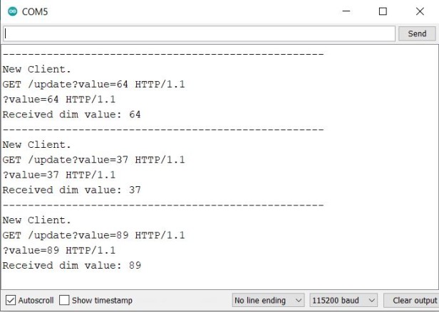
Open the serial monitor to check for connection status and the IP address assigned to the ESP32.
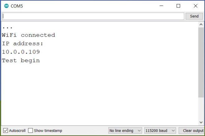
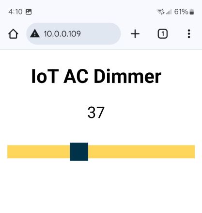
After successful connection, open a browser and enter the ESP32’s IP address (displayed on the serial monitor) to load the web server’s control page.
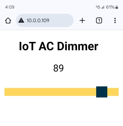
You should see a simple interface with a slider to adjust the dimming level.
Move the slider on the web page to different values (e.g., 0%, 50%, 100%) and observe the AC load’s behavior.
-
- At 0%, the load should be off.
- At 50%, the load should dim or run at half speed.
- At 100%, the load should be fully bright or at maximum speed.
Verify that the slider changes update the load’s brightness or speed in real time.
The same thing can be observed on Serial Monitor if connected via FTDI Module.
Do not touch the components or wiring while the circuit is powered. Test in a safe environment with necessary precautions for working with high-voltage AC.
Test the circuit with different types of AC loads (lamps, fans, etc.) to evaluate its performance. Measure power consumption at different dimming levels using a power meter to confirm efficiency.
This project efficiently combines hardware and software to create an IoT-enabled AC dimmer for smart home applications using ESP32 WebServer.


1 Comment
Have a look at MycilaDimmer library (https://mathieu.carbou.me/MycilaDimmer/) to make that easier 😉
This is the most comprehensive dimming library available for Arduino core on ESP32. It supports phase control and cycle stealing and correctly uses ISR functions in IRAM, which is currently not possible with esp-idf gptimer and Arduino core code directly. This library has a 12-bits resolution and supports a power LUT lookup with interpolation in order to produce a smooth variation of the power.