
 LORA Module with Arduino")
In this tutorial, we will learn about Interfacing SX1278 (Ra-02) LORA Module with Arduino. We will see SX1278 LORA & Arduino example and make a transmitter & receiver circuit. We will control the brightness of LED wirelessly using potentiometer.
Overview
In the last couple of years, there is a number of communication technologies available for interaction between IoT devices. The most popular ones are the Wi-Fi Technology and Bluetooth Module. But they have few limitations like limited range and access points. The power consumption of Wi-Fi and Bluetooth technology is high which drains the battery quickly if you go for battery-powered mobile device.
The Same thing is with the Cellular networks and LAN which also have problems of high power consumption. The LAN and Cellular network both are quite expensive to cover a wide area. In the last couple of years, IoT industries introduced lots of technologies but none of them proved to be ideal. The IoT devices need to transmit information to a long distance without using much power. So there was a revolution in the IoT field when the LoRa technology was introduced. LoRa Technology can perform very-long range transmission with low power consumption. Lora applications includes Smart water monitoring, Remote Control of Appliances, Smart Parking, Autonomous irrigation, Smart Agriculture & Soil Health Monitoring.
In this tutorial, we will learn about Interfacing SX1278 (Ra-02) LORA Module with Arduino. We will see SX1278 LORA & Arduino example and make a transmitter & receiver circuit. We will control the brightness of LED wirelessly using a potentiometer. The LoRaLib library can be used with any LoRa module if it’s based on one of the supported chips: SX1272 or SX1273, SX1276, SX1277, SX1278 or SX1279, RFM95, RFM96, RFM97, or RFM98.
Before getting started, you can visit the following posts as well:
1. ESP8266 & LoRa SX1278 Transmitter Receiver with DHT11: Check Here
2. ESP32 LoRa Sensor Data Monitoring on Web Server: Check Here
3. ESP32 & LoRa SX1278/76 Transmitter Receiver with OLED: Check Here
4. Sending Sensor Data Wirelessly with LoRa SX1278 & Arduino: Check Here
What is LoRa Technology?
![]()
The term LoRa stands for Long Range. It is a long-range, low power wireless platform that has become the de-facto technology for Internet of Things (IoT) networks worldwide. LoRa is a spread spectrum modulation technique derived from chirp spread spectrum (CSS) technology. LoRa was introduced by a company called Semtech.
LoRa modules do come in different frequency ranges, the most common being the 433MHz, 915MHz and 868MHz. This LoRa technology can be used to transmit bi-directional information to long-distance (15-20km) without consuming much power. The technology can be utilized by public, private or hybrid networks and provides greater range than Cellular networks. LoRa Technology can easily plug into existing infrastructure and enables low-cost battery-operated IoT applications.
Understanding the LoRa technology & its working
The basic principle is that information is encoded using chirp (a gradual increase or decrease in the frequency of the carrier wave over time). Before sending a message, the LoRa transmitter will send out a chirp signal to check that the band is free to send the message. Once the LoRa receiver has picked up the preamble chirp from the transmitter, the end of the preamble is signalled by the reverse chirp, which tells the LoRa transmitter that is it clear to begin transmission.

The architecture shown in this figure is explained below:
1. Devices:
It consists of LoRa Modulation, Transceivers & End-Nodes and Picocells & Gateways.
A. LoRa Modulation:LoRa Technology is the physical (PHY) silicon layer, or wireless modulation, used to create the long-range communication link.
B. Transceivers & End-Nodes: Transceivers configured with LoRa Technology are embedded into end-nodes, or sensor devices, designed for a multitude of industry applications.
C. Picocells & Gateways: Sensors capture and transmit data to gateways over distances near and far, indoor and outdoor, with minimal power requirement.
2. Network Server:
Gateways send information via Wi-Fi, Ethernet or Cellular to the network server, which is responsible for network management functions like over-the-air activation, data de-duplication, dynamic frame routing, adaptive rate control, traffic management, and administration.
3. Application Servers & Cloud IoT Services:
Applications interpret the data collected by LoRa-enabled devices, applying techniques like machine learning and artificial intelligence to solve business problems for a Smarter Planet.
Semtech SX1278 LoRa Module
The SX1276/77/78/79 transceivers feature the LoRa® long range modem that provides ultra-long range spread spectrum communication and high interference immunity whilst minimizing current consumption.

SX1278 can achieve a sensitivity of over -148dBm using a low-cost crystal. The high sensitivity combined with the integrated +20dBm power amplifier yields industry leading link budget making it optimal for any application requiring range or robustness. Lora SX1278 also provides significant advantages in both blocking and selectivity over conventional modulation techniques, solving the traditional design compromise between range, interference immunity and energy consumption. Learn more about it at: Semtech SX1278 Datasheet.
Semtech SX1278 Applications
- Automated Meter Reading
- Home and Building Automation
- Wireless Alarm and Security Systems
- Industrial Monitoring and Control
- Long range Irrigation Systems
Semtech SX1278 Pinout
There are different versions and types of SX1278 breakout board available in market. But basically all of them has same pinout as LoRa SX1278 is an SPI module. I am using this board as shown in photos below.

This module version of SX1278 has 12 pins for interfacing with microcontroller & additional two pins for antenna.

Interfacing SX1278 LoRa Module with Arduino
The LoRa module that I am using here is the SX1278 Ra-02 which operates on 433MHz. But this module is not breadboarded friendly neither it has a soldered antenna. So simply I soldered few 2.54″ male connector to make it breadboard friendly. I also soldered the antenna.

Now let us learn SX1278 Arduino Interfacing. For this, we will use two LoRa modules and two Arduino Boards to send data from one board and receive it on the other. We will use Arduino Nano at the transmitter side and Arduino Uno at the receiver side.

Let us see the circuit of transmitter and receiver part seperately.
Arduino LoRa SX1278 Transmitter
The circuit diagram for Arduino LoRa SX1278 Transmitter is given below. You can either make a pcb for this circuit or simply assemble it on the breadboard.

The LoRa SX1278 is not 5V friendly so do not supply 5V to it else the board will get damaged. Use 3.3V of Arduino to connect it to VCC pin. Connect all the GND pins to GND. Connect the RST pin to D9 and DIO0 to D2 of Arduino. Connect the SPI Pins NSS, MOSI, MISO, SCK to Arduino D10, D11, D12, D13 of Arduino respectively as shown in circuit diagram above.
Use any potentiometer like 10K and connect its middle pin to A0 of Arduino and remaining two pins to GND and 5V.

Arduino LoRa SX1278 Receiver
Similarly the circuit diagram for Arduino LoRa SX1278 Receiver is given below. You can either make a pcb for this circuit or simply assemble it on the breadboard.

The LoRa SX1278 is not 5V friendly so do not supply 5V to it else the board will get damaged. Use 3.3V of Arduino to connect it to VCC pin. Connect all the GND pins to GND. Connect the RST pin to D9 and DIO0 to D2 of Arduino. Connect the SPI Pins NSS, MOSI, MISO, SCK to Arduino D10, D11, D12, D13 of Arduino respectively as shown in circuit diagram above.
Use any LED and connect it to D3 of Arduino as shown in the photos above.

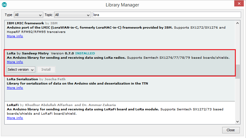
Source Code/Program
For communication between two LoRa Module, you need to have LoRa library. To get the LoRa Library go to library manager and search for LoRa and install it.
Transmitter Code
|
1 2 3 4 5 6 7 8 9 10 11 12 13 14 15 16 17 18 19 20 21 22 23 24 |
#include <SPI.h> #include <LoRa.h> int pot = A0; void setup() { Serial.begin(9600); pinMode(pot,INPUT); while (!Serial); Serial.println("LoRa Sender"); if (!LoRa.begin(433E6)) { // or 915E6, the MHz speed of yout module Serial.println("Starting LoRa failed!"); while (1); } } void loop() { int val = map(analogRead(pot),0,1024,0,255); LoRa.beginPacket(); LoRa.print(val); LoRa.endPacket(); delay(50); } |
Receiver Code
|
1 2 3 4 5 6 7 8 9 10 11 12 13 14 15 16 17 18 19 20 21 22 23 24 25 26 27 28 29 30 31 32 33 34 35 36 37 |
#include <SPI.h> #include <LoRa.h> int LED = 3; String inString = ""; // string to hold input int val = 0; void setup() { Serial.begin(9600); pinMode(LED,OUTPUT); while (!Serial); Serial.println("LoRa Receiver"); if (!LoRa.begin(433E6)) { // or 915E6 Serial.println("Starting LoRa failed!"); while (1); } } void loop() { // try to parse packet int packetSize = LoRa.parsePacket(); if (packetSize) { // read packet while (LoRa.available()) { int inChar = LoRa.read(); inString += (char)inChar; val = inString.toInt(); } inString = ""; LoRa.packetRssi(); } Serial.println(val); analogWrite(LED, val); } |
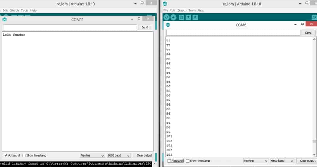
Once the code is uploaded you can start testing by rotating the knob of the potentiometer and check the brightness of the LED. You can check the value in serial monitor as well.
Video Tutorial & Guide

You can check this link as well: LoRa SX1278 & ESP8266 Transmitter Receiver with DHT11 Sensor


23 Comments
Hey! I need help wiring my SX-1278, as I can’t seem to get it to work even after following this tutorial.
The pins are labeled DIO, like digital i/o. not D10
lora module showing error to get start
is this modulation in lora tm or ask
You claim that do not connect the LoRA to 5V but you are using the 5V output pins of the Arduino UNO board. Is there no need for some level conversor? Can the LoRA accept 5V logical level from the Arduino UNO?
The SPI pins can accept 5V, you don’t need any level converter. Only the VCC requires 3.3V
Can I do this using arduino uno as a reciever ?
I tried to do 2 nodes communicating using 2 arduino uno and 2 ra 01 but the receiver doesn’t respond.
What about the arduion pins ? Do they accept 3.3.V.
The seller recommended me to use a level converter
i dont think so, the whole module use 3.3V logic. Did you check that?
Hello, I want to remotely control several relays via the Lora, is it possible? but I am having difficulty understanding the code. I do it in series with wires or in infrared. could you help me or guide me?
There is already another post in the website related to controlling the Relay using lora. You can check.
i also
Really nice tutorial, im triying to send more than one variable at the time, in the sender code i dont have problem but in the receiver code i cant figure it out, im using:
but its not working, hope you can help me.
Check some recent posts related to lora projects. I have explained the method with sample code.
I am using Arduino Due for my project and it does not work. It shows error after I send the code. Am I missing something fundamental? or it can not work on Arduino Due. I followed the tutorial. It does work perfectly fine on uno.
I do NOT connect LoRa-02 3.3V pin with Arduino-uno 3V3 pin. And, LoRa system works well as usual! I suppose LoRa-02 is powered through 5V lines of DIOx. Actually, I observed voltage 3.7V at LoRa-02 3.3V pin (open state).
Can you please share SX1278 Ra-02 Fritzing part (.fzpz)?
Not my experience. When using a 5V Arduino the circuit behaved erratically, and basically didn’t function. After much troubleshooting, I discovered the problem was with the 5V levels on the pins of the SX1278 (SX1276 in my case, although I believe the only difference is the frequency selection.) After compensating for the incorrect levels, everything worked fine.
I tried this with Ra-01 but I can control among 10m.What should I do to control long range about 10km? Should I change antenna or change program?And Can I control Sevro Motor with Ra-01 and variables resistor?
Do you have the antenna connected? If you are using the little heli which usually comes with those, make sure you solder it right at the end or it will affect tuning and thus affect performance.
Note that you’re only going to get 10 km if you are line-of-sight, including accounting for the fresnel zone. It takes very little obstacle-wise to bring that distance way down. Nevertheless, I have been able to communicate about 1/2 km from inside my house with quite a few trees in the way.
Yes, you should be able to control most anything. The Ra-01 is just sending messages, so configure your arduino (or whatever uc you are using) accordingly. Configure the receiver to do all the heavy lifting, so you are sending as little data as possible, eg, “rotate clockwise”, “go to x degrees” etc.
Use the servo library on the receiver to make things simple.
How Can we control the led with a switch? On the transmitter side!?
Hi – the pinout table at the top showing the various connections on the module is incorrect. If you look closely at the module you will see that one of the pads has square corners rather than rounded. Pin 2 is reset (not DIO1 as shown).
My arduino board just keeps restarting at LoRa.begin(433E6)
doesn’t happen with other frequencies though